Wiring Guide
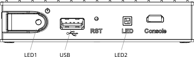
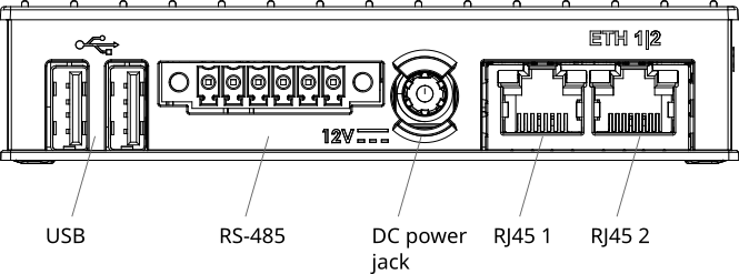
Main Unit Interfaces
| Connector | Description | Parameters | Count |
|---|---|---|---|
| DC power jack | CPU Power supply | 8VDC-36VDC min 2A. CPU power consumption 2 - 7 W | 1 |
| RJ45 1 | Ethernet | primary 1000 base-T RJ45 | 1 |
| RJ45 2 | Ethernet | secondary 10/100 base-T RJ45 | 1 |
| USB | USB 2.0 port | 3 | |
| RS-485 | RS-485 Bus | RS-485 bus needs proper line termination. baseMINI has integrated termination resistor. Connect 120Ω resistor only at the end of the bus. | 1 |
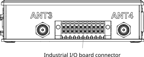
Industrial I/O Board Interfaces
| Connector | Description | Parameters | Count |
|---|---|---|---|
| Industrial I/O board connector | Isolated I/O board power supply | 24VDC 0.2A power for digital inputs, and digital outputs | 1 |
| Industrial I/O board connector | Automation Digital input | signal corresponds to the standard EN 61131-2, type 1 | 4 |
| Industrial I/O board connector | Automation Solid-state relay output | load capacity - 10.5V ~ 36V, 500mA, on resistance 0.14Ω | 4 |
| Industrial I/O board connector | Isolated RS-485 Bus | RS-485 bus needs proper line termination. baseMINI has integrated termination resistor. Connect 120Ω resistor only at the end of the bus. | 1 |
Connector Pinouts
RS-485 Connector

| Pin | Description |
|---|---|
| 1 | RS-485 B |
| 2 | RS-485 A |
| 3 | GND |
| 4 | NC |
| 5 | NC |
| 6 | GND |
Industrial I/O Board Connector

| Pin | Description |
|---|---|
| 1 | RS-485 A |
| 2 | Isolated GND |
| 3 | RS-485 B |
| 4 | NC |
| 5 | NC |
| 6 | NC |
| 7 | NC |
| 8 | NC |
| 9 | NC |
| 10 | NC |
| 11 | Digital out 0 |
| 12 | Digital out 2 |
| 13 | Digital out 1 |
| 14 | Digital out 3 |
| 15 | Digital in 0 |
| 16 | Digital in 1 |
| 17 | Digital in 2 |
| 18 | Digital in 3 |
| 19 | Positive I/O board power supply terminal |
| 20 | Negative I/O board power supply terminal |
Power Supply Wiring
DC Power Jack
| Terminal | Connection |
|---|---|
| + | 8VDC-36VDC positive (min 2A) |
| - | DC negative / GND |
Note: CPU power consumption is 2-7W.
RS-485 Bus Wiring
| Terminal | Connection |
|---|---|
| A | Data line A |
| B | Data line B |
| GND | Signal ground |
Important: RS-485 bus needs proper line termination. baseMINI has integrated termination resistor. Connect 120Ω resistor only at the end of the bus.
Industrial I/O Board Wiring
Power Supply
The I/O board requires isolated 24VDC 0.2A power supply connected to pins 19 (+) and 20 (-).
Digital Inputs
Digital inputs correspond to the standard EN 61131-2, type 1.
| Pin | Input |
|---|---|
| 15 | Digital in 0 |
| 16 | Digital in 1 |
| 17 | Digital in 2 |
| 18 | Digital in 3 |
Digital Outputs
Solid-state relay outputs with load capacity 10.5V ~ 36V, 500mA, on resistance 0.14Ω.
| Pin | Output |
|---|---|
| 11 | Digital out 0 |
| 13 | Digital out 1 |
| 12 | Digital out 2 |
| 14 | Digital out 3 |