Wiring Guide
Interfaces
| Connector | Description | Parameters | Count |
|---|---|---|---|
| DC | Security and CPU Power supply | 12VDC-24VDC min 2.5A or 16VAC 60VA. CPU power consumption ≤ 5 VA | 1 |
| io24V | Isolated I/O Automation board Power supply | 24VDC 0.2A power for analog inputs, digital inputs, digital outputs and relay outputs | 1 |
| RJ45 | Ethernet | 10/100 base-T RJ45 | 1 |
| RS485 | RS-485 Bus | RS-485 bus needs proper line termination. Terminate RS-485 bus with 120Ohm resistors, one at each end of the line. baseSAFE controller has integrated termination resistors. Set dipswitch SW2 position 1 to "on" to enable termination resistor. | 2 |
| USB | USB 2.0 port | 2 | |
| Z | Security Zone inputs | See wiring section below | 7 |
| PGM | Security Solid-state PGM output | load capacity - 60Vp, 100mA, on resistance 16Ω | 2 |
| BELL | Security Bell monitored output | 12V 1A | 1 |
| BAT | Security Battery | 12V maximum charging current 700mA. Battery is used as a backup power supply for security and CPU | 1 |
| AUX | Auxiliary equipment power supply | 12VDC 2A | 1 |
| AI | Automation Analog input | handles signals in the range from 0 to 10V, 0mA to 20mA or PT1000 | 4 |
| DI | Automation Digital input | signal corresponds to the standard EN 61131-2, type 1 | 8 |
| R | Automation Relay output | load capacity - 250VAC 5A cos(ϕ) = 1 | 8 |
| DO | Automation Solid-state relay output | load capacity - 60Vp, 100mA, on resistance 16Ω | 4 |
Note: Each Automation analog input can be configured to 3 different modes: 0-10V, 0-20mA, or PT1000.
Main Unit Connectors
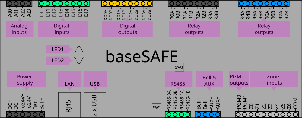

| Connector | Details |
|---|---|
| AI0 - AI4 | Analog inputs |
| DI0 - DI7 | Digital inputs |
| DO0 - DO3 | Solid-state relay outputs |
| R0 - R7 | Relay outputs |
| DC+ or AC/DC | Main power supply terminal |
| DC- or AC/DC | Main power supply terminal |
| io24V+ | I/O positive power supply terminal |
| io24V- | I/O negative power supply terminal |
| Bat+ | Battery positive terminal |
| Bat- | Battery negative terminal |
| USB1 - USB2 | USB 2.0 ports |
| RJ45 | Ethernet 10/100 base-T port |
| RS485-0A | RS-485 bus 0 positive terminal |
| RS485-0B | RS-485 bus 0 negative terminal |
| RS485-1A | RS-485 bus 1 positive terminal |
| RS485-1B | RS-485 bus 1 negative terminal |
| Bell+ | Bell positive terminal |
| Bell- | Bell negative terminal |
| AUX+ | Positive power supply terminal for auxiliary equipment |
| AUX- | Negative power supply terminal for auxiliary equipment |
| PGM0 - PGM1 | Security Solid-state PGM outputs |
| Z0 - Z7 | Security zone terminals |
| COM | Security common terminal |
General Wiring
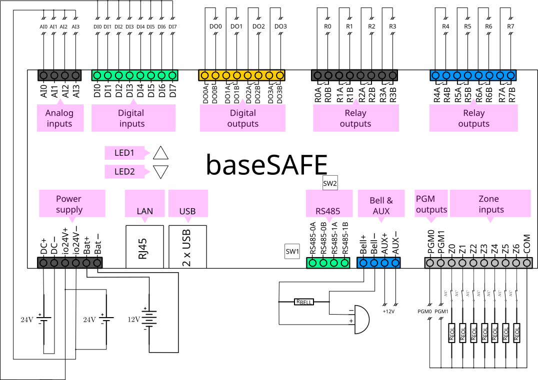
Power Supply Wiring
Main Power
| Terminal | Connection |
|---|---|
| DC+ or AC/DC | 12VDC-24VDC positive (min 2.5A) or 16VAC |
| DC- or AC/DC | DC negative / GND or AC |
Note: CPU power consumption ≤ 5 VA.
I/O Board Power
| Terminal | Connection |
|---|---|
| io24V+ | 24VDC positive (0.2A) |
| io24V- | 24VDC negative / GND |
Battery Backup
| Terminal | Connection |
|---|---|
| Bat+ | 12V battery positive |
| Bat- | 12V battery negative |
Note: Maximum charging current 700mA. Battery provides backup power for security and CPU.
RS-485 Bus Wiring
| Terminal | Connection |
|---|---|
| RS485-0A / RS485-1A | Data line A (positive) |
| RS485-0B / RS485-1B | Data line B (negative) |
Important: RS-485 bus needs proper line termination with 120Ω resistors at each end. baseSAFE has integrated termination resistors - set dipswitch SW2 position 1 to "on" to enable.
Security Zone Wiring
| Wiring with no resistors | Wiring with EOL resistor | Wiring with EOL and Zone resistor |
|---|---|---|
 | 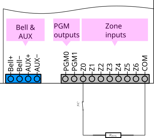 | 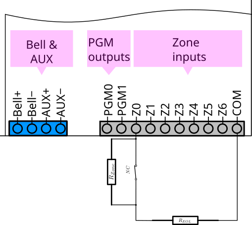 |
Digital Inputs
Digital inputs correspond to the standard EN 61131-2, type 1.
| Terminal | Input |
|---|---|
| DI0 | Digital input 0 |
| DI1 | Digital input 1 |
| DI2 | Digital input 2 |
| DI3 | Digital input 3 |
| DI4 | Digital input 4 |
| DI5 | Digital input 5 |
| DI6 | Digital input 6 |
| DI7 | Digital input 7 |
Digital Outputs
Solid-state relay outputs with load capacity 60Vp, 100mA, on resistance 16Ω.
| Terminal | Output |
|---|---|
| DO0 | Digital output 0 |
| DO1 | Digital output 1 |
| DO2 | Digital output 2 |
| DO3 | Digital output 3 |
Relay Outputs
Relay outputs with load capacity 250VAC 5A cos(ϕ) = 1.
| Terminal | Output |
|---|---|
| R0 | Relay output 0 |
| R1 | Relay output 1 |
| R2 | Relay output 2 |
| R3 | Relay output 3 |
| R4 | Relay output 4 |
| R5 | Relay output 5 |
| R6 | Relay output 6 |
| R7 | Relay output 7 |
Analog Inputs
| Terminal | Input |
|---|---|
| AI0 | Analog input 0 |
| AI1 | Analog input 1 |
| AI2 | Analog input 2 |
| AI3 | Analog input 3 |
Each analog input can be configured for:
- 0-10V voltage input
- 0-20mA current input
- PT1000 temperature sensor